
Shielding Effectiveness and Velocity of Propagation: How Coaxial Cable Fights a Two-Front War
Key Takeaways
- Shielding effectiveness is the ratio of internal energy to radiated energy — higher shielding means less leakage in both directions, protecting both the signal and surrounding equipment.
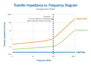
- At low frequencies (<100 MHz), shielding is governed by transfer impedance; at high frequencies, by the optical coverage of the outer conductor construction.
- The connector interface is the most vulnerable point in the shielding system — 360-degree contact at the termination is non-negotiable for maintaining rated shielding performance.
- Velocity of propagation is set by the dielectric constant of the insulating material; lower dielectric constant equals higher velocity and lower time delay per unit length.
- For phase-sensitive applications, Vp consistency across temperature is more important than the absolute velocity value — and PTFE’s phase transition near room temperature must be factored into system design.
- Higher-velocity dielectrics tend to be less mechanically dense, making them more sensitive to dimensional changes caused by flexing, crushing, or contamination ingress.
A coaxial cable is fighting on two fronts simultaneously. On the first front, it must prevent the electromagnetic energy it carries from leaking outward where it can interfere with adjacent electronics or degrade the integrity of the signal. On the second front, it must prevent external electromagnetic interference from leaking inward, corrupting the signal it was entrusted to carry. The weapon it uses for both is the outer conductor, and the effectiveness of that weapon is entirely determined by how that conductor is constructed.
At the same time, the insulating material between the conductors — the dielectric — does something that is easy to overlook until it causes a system problem: it controls the speed at which the RF signal travels through the cable. That speed, expressed as a percentage of the speed of light in vacuum, is the velocity of propagation. In systems that depend on precise timing or electrical length — phased array antennas, GPS, radar — the velocity of propagation isn’t just a data sheet footnote. It is a core design parameter.
These two characteristics, shielding effectiveness and velocity of propagation, both originate in the same physical structure: the dielectric and outer conductor. Understanding how construction choices affect both is essential for engineers specifying cables in dense, interference-prone, or timing-sensitive environments.
Shielding Effectiveness: Keeping the Signal In and the Noise Out
Shielding effectiveness is defined as the ratio of the electromagnetic energy inside the cable to the energy that radiates from the outside of the cable. It is typically expressed in decibels (dBc), and the reference benchmark is a solid metal tube — the construction used in semi-rigid cables — which provides theoretical 100% coverage and defines the upper bound of what any flexible cable construction must be measured against.
At lower frequencies (up to approximately 100 MHz), shielding effectiveness is determined primarily by the transfer impedance of the shield; a measure of how much voltage is induced on the outer surface of the shield by a current flowing on the inner surface. Lower transfer impedance equals better shielding. As frequency increases above 100 MHz, the dominant shielding mechanism transitions to the optical coverage of the outer conductor; the physical percentage of the cable’s circumference that is covered by conducting material.
Shield Construction Options: A Performance Hierarchy
The coaxial cable industry has developed a range of outer conductor constructions that represent increasing levels of shielding performance, each with its own trade-offs in flexibility, weight, and cost:
 Single Braid (70%–95% optical coverage): The baseline flexible construction. Round copper wires woven in a helical pattern. Coverage depends on the angle and density of the weave. Suitable for most commercial applications where shielding requirements are moderate.
- Double Braid (>95% coverage): Two single braids layered without insulation between them. Provides meaningfully improved shielding isolation, particularly at frequencies above 100 MHz where optical coverage dominates.
- Triaxial (Two separated braids): Two braids with an insulating layer between them. Allows each braid to be driven at a different potential, enabling differential measurement techniques that further improve common-mode rejection.
- Flat Braid with Helical Wrap: To achieve greater optical coverage, we use woven flat braids using silver plated copper. The TCOM®, StripFlex® and SFT cable families use this approach to achieve semi-rigid levels of isolation in a hand-formable package.
- Spiral Flat Strips with Helical Wrap (~100% coverage): Instead of round wires, these use flat copper strips wound in a non-overlapping spiral or a “barber pole” pattern. The flat strips provide approaching 100% optical coverage while retaining more flexibility than a solid tube. MilTech® cable uses this spiral outer-conductor construction to combine high shielding effectiveness with the flexibility needed for routing and installation.
- Solid Sheath (100% coverage): Aluminum or copper tubing. The benchmark for shielding effectiveness. Zero gaps, zero optical coverage variation with frequency. The trade-off is rigidity; these cables cannot be repeatedly flexed without mechanical failure.
 Single Braid (70%–95% optical coverage): The baseline flexible construction. Round copper wires woven in a helical pattern. Coverage depends on the angle and density of the weave. Suitable for most commercial applications where shielding requirements are moderate.

The Connector Is the Weakest Link
Shielding is only as strong as its weakest point, and in a cable assembly, that weakest point is the connector interface. A cable with excellent optical coverage can have its shielding performance dramatically degraded by a connector that fails to maintain 360-degree contact with the outer conductor at the termination point. Any gap in that circumferential contact is effectively a slot antenna; a point where electromagnetic energy can both radiate outward and enter the cable.
This failure mode is also an impedance event, not just a shielding event. A connector that breaks 360-degree contact with the outer conductor doesn’t just open a leakage path, it creates a geometric discontinuity that generates reflected power. That means a shielding failure at the connector is simultaneously a VSWR failure, and vice versa. The two performance degradation modes share the same physical root cause.
Velocity of Propagation: Why Signal Timing Depends on the Dielectric
 The velocity at which an RF signal travels through a coaxial cable is determined almost entirely by the dielectric constant of the insulating material between the conductors. In a vacuum, electromagnetic energy travels at the speed of light. Inside a coaxial cable, the dielectric slows it down; the higher the dielectric constant, the slower the signal travels.
Velocity of propagation (Vp) is expressed as a percentage of the speed of light in vacuum. A cable with Vp = 66% means the signal travels at 66% of the speed of light through that cable. The time delay per unit length follows directly: a cable with 81% velocity accumulates approximately 1.2 nanoseconds of delay per foot, while a solid polyethylene cable at 66% velocity accumulates approximately 1.54 nanoseconds per foot.

Why Velocity Stability Matters as Much as Velocity Value
For many applications, the absolute velocity of propagation is less important than its consistency — how much it changes with temperature, flexure, and time. In phased array antennas, for example, multiple cables must deliver signals with precisely matched electrical lengths to maintain beam pointing accuracy. A consistent Vp across all cables and temperatures is more valuable than a high absolute Vp that shifts as conditions change.
This is where dielectric material selection becomes a nuanced decision. PTFE has excellent high-frequency loss characteristics, but it undergoes a well-documented mechanical phase transition between approximately 18°C and 22°C (64°F to 72°F) — commonly called the “Teflon knee” — where its density changes by about 1.5%. This density shift alters the dielectric constant and causes a corresponding abrupt change in electrical length. For precision phase-sensitive systems, this transition must be anticipated and compensated for in the system design.
The “Teflon knee” is also one of the reasons why temperature correction factors for attenuation are more complex with PTFE than with polyethylene. The relationship between dielectric material, temperature, attenuation, and velocity is a set of interconnected variables; changing one changes all of them.
Times Microwave Systems’ PhaseTrack® cable family is designed to address this phase stability challenge. PhaseTrack uses TF4™ dielectric technology, which does not exhibit the room-temperature phase transition associated with conventional PTFE. This helps provide more consistent phase performance across temperature, making PhaseTrack well suited for applications where maintaining electrical length and phase stability is critical.
The Physical Construction Connection
 Higher-velocity dielectrics are generally those that incorporate more air into the structure — foamed or expanded materials rather than solid ones. This air incorporation reduces the dielectric constant, which raises Vp and lowers attenuation simultaneously. However, it also makes the dielectric structure less mechanically dense, and that has consequences that extend beyond the cable’s electrical spec sheet.
A cable with an expanded or foamed dielectric that is over-bent or crushed will not only degrade in VSWR because its geometry has changed, but may also shift in velocity, because the dielectric structure itself has been physically compressed and its effective dielectric constant altered. This means that in phase-sensitive systems, mechanical damage to the cable doesn’t just affect signal amplitude; it changes the timing of the signal as well.
This is one of the clearest illustrations of how mechanical and electrical performance are inseparable in RF cable design. Every shielding construction choice that affects optical coverage also has a corresponding effect on the cable’s mechanical behavior: its minimum bend radius, its crush resistance, its susceptibility to dielectric deformation under clamping pressure.
FAQ
What is shielding effectiveness in coaxial cable and how is it measured?
Shielding effectiveness is the ratio of electromagnetic energy inside the cable to the energy that radiates from its outer surface, expressed in dBc. It is measured against a solid metal tube as the reference benchmark. Below 100 MHz, it is governed by the shield’s transfer impedance; above 100 MHz, it is governed by the optical coverage — the physical percentage of the cable’s circumference covered by conducting material.
Why does a cable with good shielding still leak signal at connectors?
The connector interface is the most common point of shielding failure. Any gap in the 360-degree contact between the connector and the cable’s outer conductor acts as a slot antenna, allowing electromagnetic energy to both radiate outward and enter the cable. A perfectly shielded cable with a poorly terminated connector will have shielding performance limited by that connector, not by the cable itself.
What is velocity of propagation in coaxial cable and why does it matter?
Velocity of propagation (Vp) is the speed at which an RF signal travels through a cable, expressed as a percentage of the speed of light in vacuum. It is determined by the dielectric constant of the insulating material. It matters because it sets the time delay per unit length; critical in phased arrays, GPS, and radar systems where precise signal timing and matched electrical lengths are required.
What is the “Teflon knee” and how does it affect cable performance?
PTFE (Teflon) undergoes a mechanical phase transition between approximately 18°C and 22°C where its density changes by about 1.5%. This shift alters the dielectric constant, causing an abrupt change in both electrical length and velocity of propagation through that temperature range. For phase-sensitive systems, this transition must be accounted for in the system design to prevent beam pointing errors or timing drift near room temperature.
Subscribe to our newsletter!
Interested in receiving email newsletters and other updates from Times? Subscribe now!